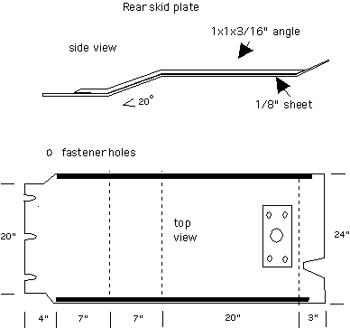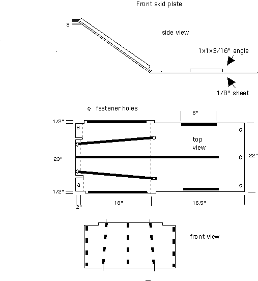

Dashed lines in top view indicate where bends are.
The fastener holes shown in top view would go into front cross member,
front a-arm brace, and rear a-arm brace to be added.
The rear skid plate looks something like the sketch below

The bend in front would is positioned to clear anti-roll bar. I might have moved this bend 1-2" further forward so that when you come down off the front wheels you land on the sloped section of the skidplate (obviously the position of this bend depends on the shape of the sway bar, and tire size. The bend in the middle would be positioned to clear driveshaft. The bend in the back is just to give it a little ramp effect behind the transfer case cross-member.
Oops, I forgot to add the nice hooks to the pictures...
Thanks again for you help with this.