| Rock Analog Experiments and notes by Dr. Win Means: 1. Technique |
Click image to enlarge (~1MB) |
| These images illustrate the progressive
development of geological-looking microstructures in deforming
crystalline materials. The sample materials are not rocks, but the
histories displayed may nevertheless be of interest to students and
others learning about microstructures in rocks, as explained more fully
in the notes below and in the review article: "Synkinematic microscopy
of transparent polycrystals" by W.D. Means (Journal of Structural
Geology, volume 11, number 12, pages 163-174, 1989). Features of
interest in the pictures are referred to by their coordinates on the
screen with the origin at the upper left-hand corner. The long
dimension of the image (usually horizontal) is 100 length units and the
short dimension is about 66 units. The coordinates are employed most
easily if individual images are saved to hard disk and opened with a
graphics application that features rulers. The coordinates of very
small features may be inexact in some cases, because of variations
between digital images and the original cardboard-mount slides. I thank Scott Paterson (University of Southern California) for requesting the first set of these images and thereby suggesting to me that other colleagues might also be able to use the pictures in their teaching. I also thank the National Science Foundation for supporting the research (1980-1988) from which the images have been drawn. I thank Declan de Paor for constructing this web-based version of the set. |
|
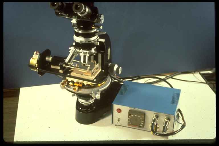
| 1. Stage-mounted press designed by J.L. Urai). Motor (15,30), screw-jack housing (25,30) jack blade that loads the sample assembly (35,32; silver piece just to the right of left-hand objective), sample block with internal heating units, cooling conduits, and slot through which light passes (40,35), and control unit (70,50). This apparatus, with an upgraded control unit but without the x-y stage shown (brass knobs facing viewer) is available commercially from: FUTRON, Rembrandtlaan 13, 3723 BG Bilthoven, The Netherlands. The 1990 price of $5,236 included charges for additional motors (for different strain rates) and miscellaneous small tools and accessories. |
|
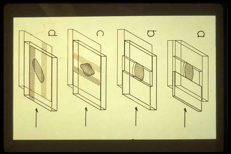
| 2. Schematic diagrams of four different sample assemblies. Top of sample is shaded. (a) Sample deformed by pushing piston between two glass slides. (b) Sample deformed by steps on glass slides. (c) Sample deformed using frosted "grips" ground onto glass slides. Heavy ornament is grip on upper slide. Light ornament is grip on lower slide. (a), (b), and (c) are for pure shearing. (d) Frosted grips arranged parallel to direction of relative movement of slides, for simple shearing. |
|
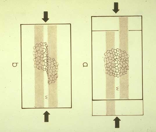
| 3. Another view of frosted-grip assembly for simple shearing. This is the technique used to obtain most of the following photographs. It was introduced about 15 years ago (Means, 1981, The concept of steady-state foliation. Tectonophysics 78, 179-199). The deformation in the sample is often localized in the window area (W) between the grips, as shown here. |
|